Structural Engineering Fundamentals: Load Paths, Equilibrium, and Free-Body Diagrams
Master the fundamentals of structural engineering with this comprehensive guide covering static equilibrium, free-body diagrams, internal forces, load paths, wing deflection analysis for different maneuver conditions, and spar orientation effects on stiffness. Essential knowledge for conceptual design work and design reviews.
Understanding how forces move through structures is fundamental to engineering design. Whether you're performing conceptual design work, supporting design reviews, or analyzing an aerospace component, mastering equilibrium, free-body diagrams, and load paths will help you explain structural behavior clearly and make sound engineering decisions.
Table of Contents
- Static Equilibrium
- Free-Body Diagrams (FBD)
- Internal Forces in Members
- Load Paths and Stiffness
- Joints and Interfaces
- Aerospace Structures
- Static vs. Dynamic Loads
- Wing Deflection Analysis: Maneuver Loads and Tip Masses
- Spar Orientation and Wing Stiffness
- Applying These Concepts in Design Reviews
1. Static Equilibrium
A body is in static equilibrium when it does not accelerate—neither translationally nor rotationally. For this condition to hold, two fundamental requirements must be satisfied:
The first equation states that the vector sum of all forces acting on the body must equal zero. The second requires that the sum of all moments (torques) about any point must also equal zero. These conditions ensure the structure is balanced and form the starting point for any structural analysis.
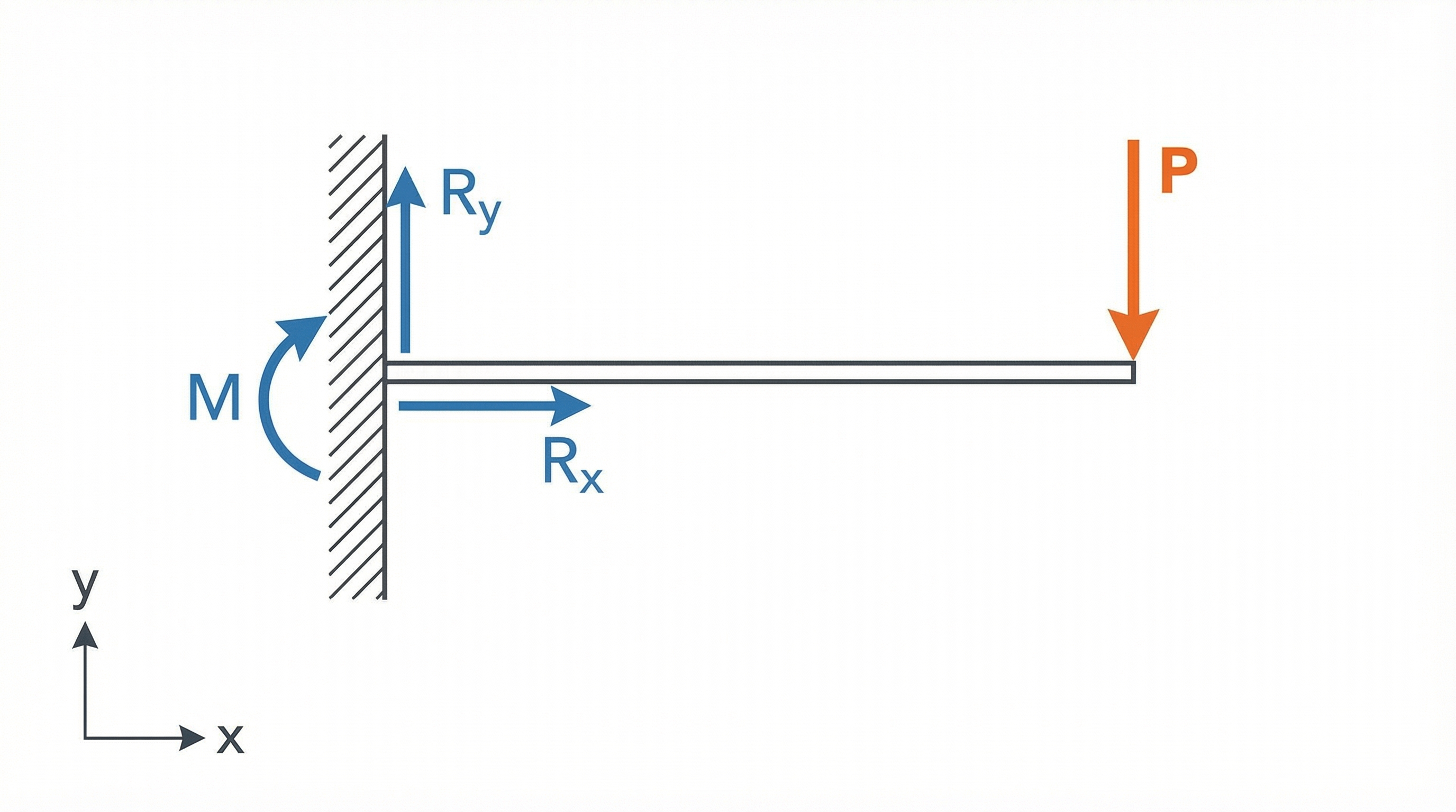
Figure 1: Free-body diagram of a cantilever beam showing applied load P, reaction forces Rx and Ry, and reaction moment M at the fixed support.
2. Free-Body Diagrams (FBD)
The free-body diagram is the engineer's most powerful analytical tool. Creating an accurate FBD involves three essential steps:
Step 1: Isolate the Body
Detach the member or component from its supports and surroundings. Imagine it floating free in space and draw it separately from the original sketch.
Step 2: Identify Loads and Reactions
Show all external forces acting on the body:
- Applied loads (forces, pressures, weights)
- Reaction forces at supports or connections
- Reaction moments at fixed supports
Replace each support with its corresponding reaction forces and moments based on the support type.
Step 3: Label Clearly
Indicate magnitudes, directions, and coordinate axes. A well-drawn FBD makes the equilibrium equations obvious and helps trace how loads enter and exit the component.
| Support Type | Reaction Forces | Reaction Moments |
|---|---|---|
| Roller | 1 force (perpendicular) | None |
| Pin/Hinge | 2 forces (Rx, Ry) | None |
| Fixed/Cantilever | 2 forces (Rx, Ry) | 1 moment (M) |
3. Internal Forces in Members
When a structure is loaded, each member develops internal actions to resist external forces. Understanding these internal forces is crucial for sizing members and selecting materials.
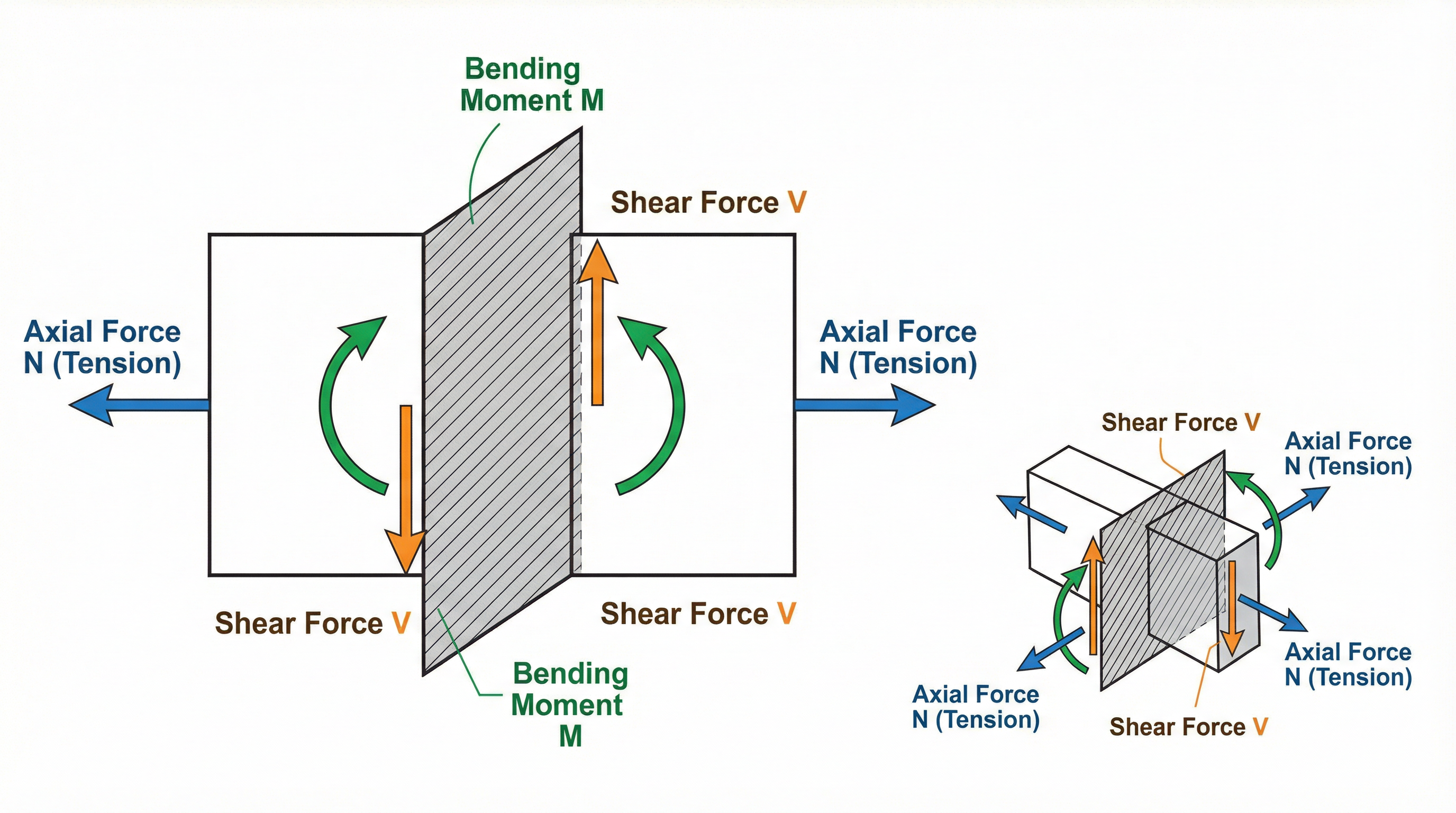
Figure 2: Internal forces at a beam cross-section: axial force N, shear force V, and bending moment M.
Axial (Normal) Force
Tension or compression acting along the member's longitudinal axis. Defined as the algebraic sum of axial forces on either side of a section:
Shear Force
A sliding force perpendicular to the member's length. Defined as the sum of transverse forces on either side of a section:
Bending Moment
The rotational effect causing curvature in the member. Equal to the sum of moments of forces on either side of the section:
In three-dimensional analysis, a general section experiences:
- 1 normal force (along the member axis)
- 2 shear forces (perpendicular to the axis)
- 3 moments (1 torsion + 2 bending)
Use shear-moment diagrams or sectional cuts to compute these internal forces. Remember that these quantities vary along the member length, and sign conventions (positive/negative directions) must be consistently applied.
4. Load Paths and Stiffness
A load path is the route that structural loads follow through a building or machine to reach supports or the ground. Effective design ensures loads transfer without failure or excessive deformation.
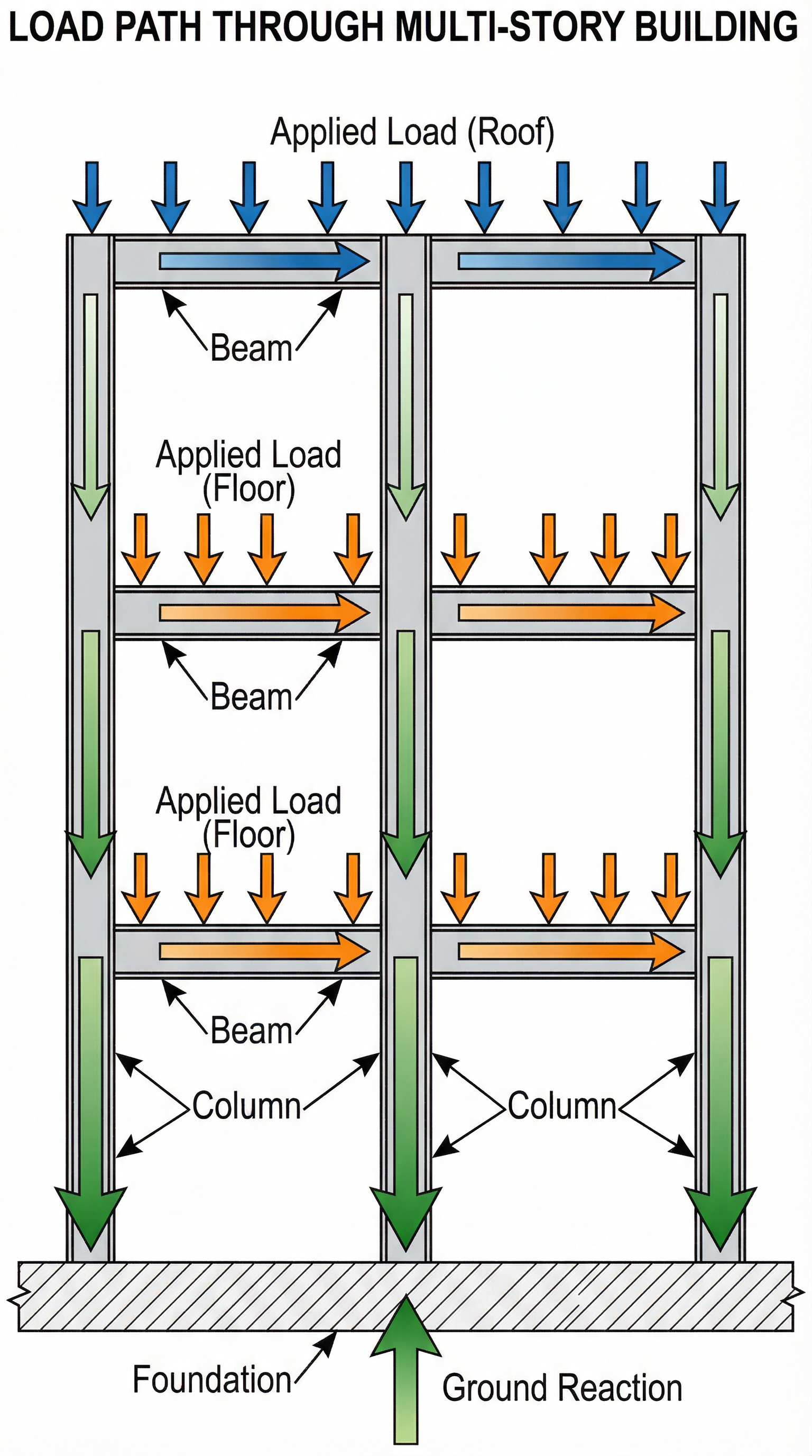
Figure 3: Load path through a multi-story building showing how applied loads transfer from beams to columns to foundation.
The Stiffness Principle
Loads tend to follow the stiffest available path. When structural elements have different stiffnesses, the stiffer element carries proportionally more load. This principle has important implications:
Where F is the force carried and k is the stiffness of each element.
Changes in material properties or geometric stiffness (such as adding stiffeners or increasing cross-sectional area) can alter the load path and redistribute forces throughout the structure.
Tracing Load Paths
During conceptual design work or when supporting design reviews, practice tracing how a load:
- Enters the system (point of application)
- Travels through members (beams, columns, connections)
- Exits at reactions (supports, foundations)
This narrative approach demonstrates engineering intuition and is essential for effective design communication and review discussions.
5. Joints and Interfaces
Joints—the connections between structural members—are often the weakest points in a structure. Poor joint design can lead to failure even when individual members are adequately sized.
Critical Joint Considerations
- Adequate reinforcement at stress concentrations
- Proper anchorage for load transfer
- Sufficient ductility for energy absorption
- Redundancy for alternate load paths
These factors are especially important in seismic or dynamic environments where connections must withstand cyclic loading and potential overloads.
Bolted Joints
Bolted connections clamp parts together using preload—the tension in the bolt created during tightening. Key aspects include:
| Component | Function |
|---|---|
| Bolt Preload | Creates clamping force, prevents joint slip |
| Washers | Distribute load, reduce bearing stress |
| Proper Torque | Ensures consistent preload, prevents fatigue |
Understanding whether a bolted joint carries shear through friction (due to preload) or direct bearing (bolt shank against hole) is essential for proper design and analysis.
6. Aerospace Structures
Aerospace structures exemplify efficient load path design, where weight minimization is paramount while maintaining structural integrity.
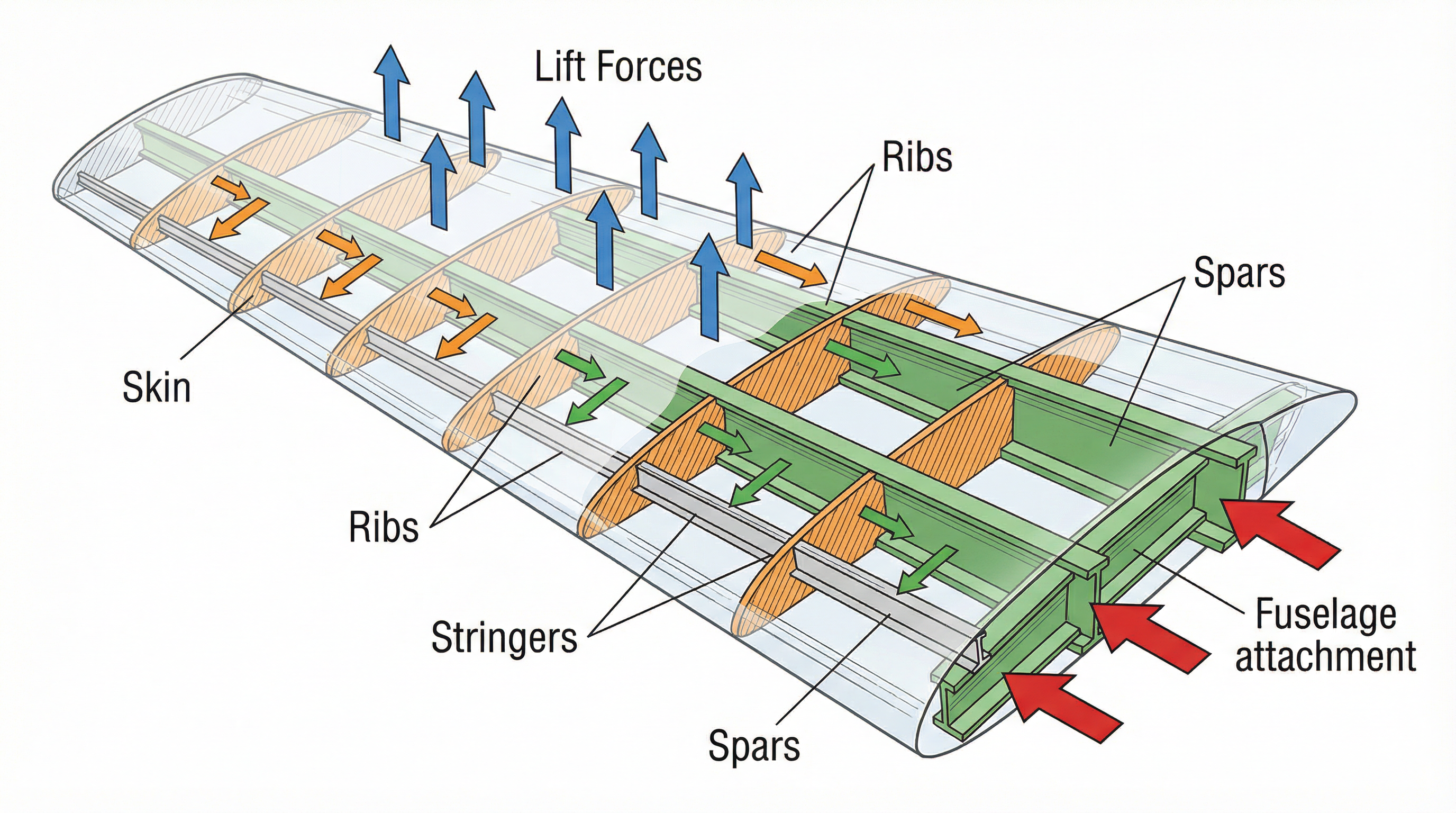
Figure 4: Aircraft wing internal structure showing skin, ribs, spars, stringers, and the load path from lift forces to fuselage attachment.
Wing Load Path
The transfer of lift forces follows a specific hierarchy:
- Skin → receives aerodynamic pressure
- Ribs → transfer loads from skin, maintain cross-section shape
- Spars → main structural members carrying bending loads spanwise
- Fuselage → receives loads at wing attachment points
Stringers (longitudinal stiffeners) transfer loads from the skin to ribs and spars while preventing skin buckling.
Fuselage Structure
In a semi-monocoque fuselage design:
- Skin carries a portion of axial and shear loads
- Frames/Bulkheads maintain shape and provide stiffening
- Longerons run longitudinally, carrying bending and torsional loads
- Stringers reinforce skin against buckling
The key principle: thin shells and stiffeners share loads efficiently, and load paths are designed to minimize weight while providing redundancy.
7. Static vs. Dynamic Loads
Understanding the distinction between static and dynamic loading is crucial for proper structural analysis and design.
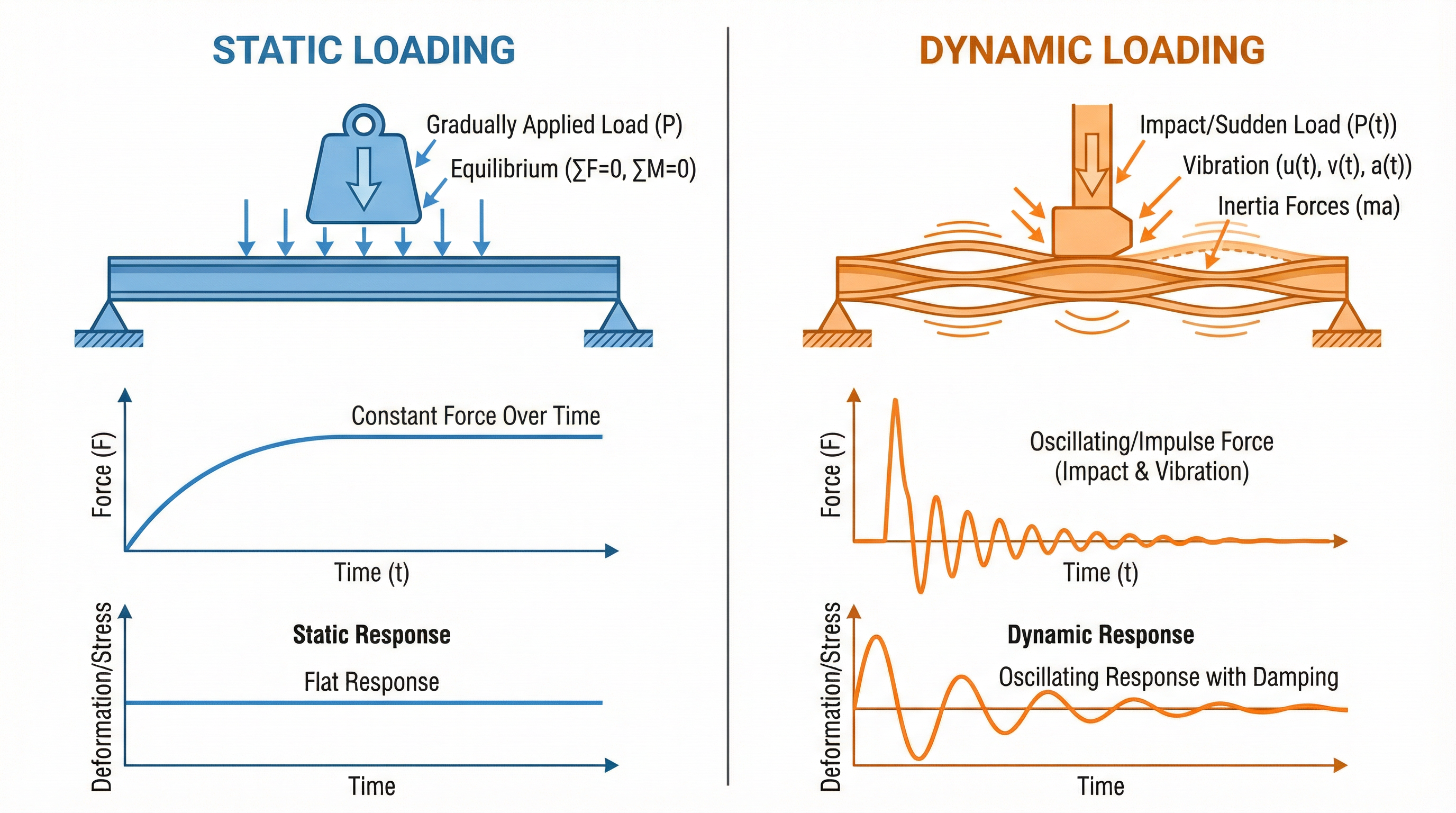
Figure 5: Comparison of static and dynamic loading showing force application, structural response, and time-history behavior.
Static Loads
Static loads are applied slowly and reach their maximum value without significant time variation. The structural response is quasi-steady, and standard equilibrium analysis is sufficient:
Dynamic Loads
Dynamic loads (vibration, shock, acoustic) are applied suddenly and vary rapidly with time. The equation of motion includes inertia:
Where:
- = mass
- = damping coefficient
- = stiffness
- = time-varying force
Key differences under dynamic loading:
- Inertia forces arise, depending on mass and acceleration
- Oscillations can occur at natural frequencies
- Load paths may differ because mass participates in carrying loads
- High stresses can develop even when static loads are small
Important: Vibration and shock can cause high stresses and fatigue damage even when equivalent static loads would be negligible. Always consider dynamic effects in design.
8. Wing Deflection Analysis: Maneuver Loads and Tip Masses
Understanding wing deflection under various loading conditions is critical during conceptual design and design reviews. This section covers the fundamental approach to calculating wing deflection for different maneuver cases and examines the effect of adding tip masses such as tilt rotors.
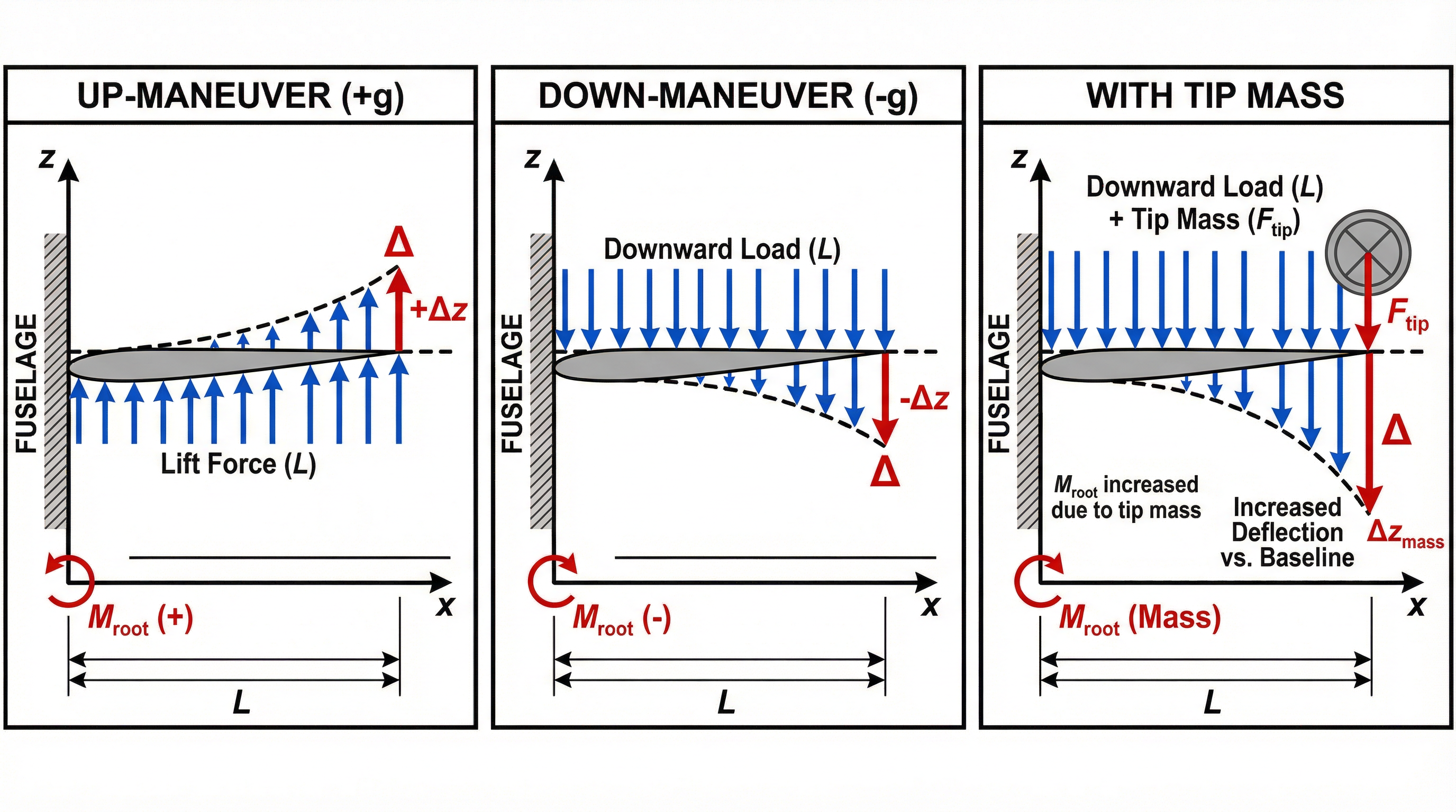
Figure 6: Wing deflection comparison showing up-maneuver (positive g), down-maneuver (negative g), and the effect of a tilt rotor tip mass.
Modeling the Wing as a Cantilever Beam
For conceptual analysis, a wing can be modeled as a cantilever beam fixed at the fuselage attachment. The key parameters are:
- Span (): Wing semi-span from root to tip
- Bending stiffness (): Product of elastic modulus and area moment of inertia
- Distributed lift load (): Lift per unit span (typically varies elliptically)
- Tip mass (): Any concentrated mass at the wing tip (engines, pods, rotors)
Derivation of Wing Tip Displacement Equation
Understanding how the wing tip displacement equation is derived from first principles provides deeper insight into structural behavior and enables engineers to adapt the analysis for non-standard configurations.
Starting Point: Euler-Bernoulli Beam Theory
The fundamental equation governing beam deflection comes from Euler-Bernoulli beam theory, which relates the bending moment to the curvature of the beam:
Where:
- = elastic modulus of the wing material
- = area moment of inertia of the cross-section about the bending axis
- = vertical deflection at position
- = spanwise position measured from the wing root
Step 1: Define the Loading Condition
For a wing under uniformly distributed lift load (force per unit length), the shear force and bending moment at any spanwise location are found by integration from the tip:
Shear Force:
Bending Moment:
Note: The moment is positive (causing upward curvature) because lift acts upward.
Step 2: Integrate the Beam Equation
Substituting the moment expression into the Euler-Bernoulli equation:
First Integration (Slope):
Second Integration (Deflection):
Step 3: Apply Boundary Conditions
For a cantilever beam (wing fixed at the root):
At (wing root):
- Deflection is zero:
- Slope is zero:
Applying the slope boundary condition at :
Applying the deflection boundary condition at :
Step 4: Final Deflection Equation
Substituting the constants back and simplifying, the deflection at any point along the span is:
Evaluating at the wing tip where :
This is the classic result for a cantilever beam with uniformly distributed load.
Alternative: Energy Methods (Castigliano's Theorem)
The same result can be obtained using Castigliano's theorem, which states that the deflection at a point equals the partial derivative of strain energy with respect to the force at that point:
This approach is particularly useful when combining multiple load cases or for statically indeterminate structures.
Extension to Concentrated Tip Mass
For a concentrated mass at the wing tip (such as a tilt rotor), the additional deflection comes from the standard cantilever result for a point load at the free end:
Total Deflection with Tip Mass
The total wing tip deflection under combined distributed lift and tip mass is:
Where is the load factor (g-loading) during the maneuver.
Key Insights from the Derivation
-
Fourth-power dependence on span: Deflection scales as for distributed loads, making span increases very costly structurally.
-
Inverse relationship with EI: Doubling the bending stiffness halves the deflection—this drives spar sizing decisions.
-
Tip mass amplification: The dependence for tip loads means tip masses have outsized effects on deflection compared to distributed loads.
-
Superposition applies: For linear elastic analysis, deflections from different load cases can be added directly.
Up-Maneuver (Positive g-Loading)
During a pull-up maneuver, the wing experiences increased lift to generate the required load factor . The total lift must equal where is the aircraft weight.
Load distribution: Lift acts upward, creating a bending moment that curves the wing upward (tips deflect up relative to root).
For a uniformly distributed load approximation:
For a more realistic elliptical lift distribution:
The bending moment is maximum at the wing root:
Down-Maneuver (Negative g-Loading)
During a push-over or inverted flight, the wing experiences negative lift (or reduced lift below 1g). The wing bends downward relative to its unloaded position.
Key considerations:
- The magnitude of deflection follows the same equations but with reversed sign
- Negative g limits are typically lower than positive g limits (e.g., -1g to -3g vs. +2.5g to +9g)
- The upper wing skin, normally in compression during positive g, goes into tension
- Fuel sloshing and negative g fuel system design become considerations
Effect of Tilt Rotor at Wing Tip
Adding a tilt rotor (or any significant tip mass) fundamentally changes the wing's structural behavior:
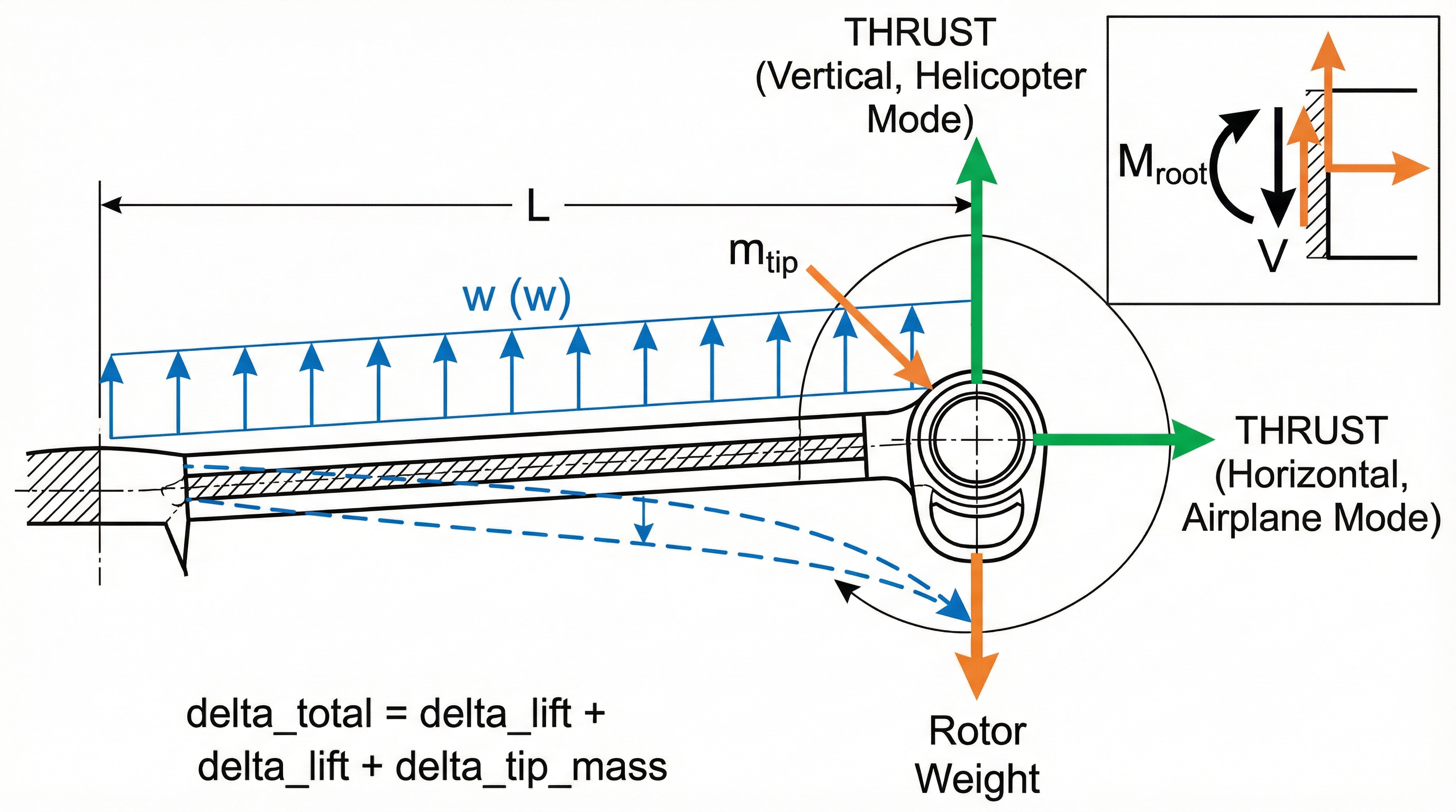
Figure 7: Tilt rotor configuration showing additional tip mass effects on wing deflection and the resulting increased root bending moment.
Increased Static Deflection:
The tip mass adds a concentrated load that increases deflection:
Increased Root Bending Moment:
Dynamic Considerations:
The tip mass lowers the wing's natural frequency:
Adding tip mass increases , reducing . This has implications for:
- Flutter speed margins
- Gust response
- Whirl flutter (specific to tilt rotors)
Thrust Effects:
When the tilt rotor produces thrust, additional loads include:
- Vertical thrust component (in helicopter mode): Relieves wing bending in hover
- Horizontal thrust (in airplane mode): Creates additional wing torsion
- Gyroscopic moments: During transition between modes
Quick Estimation Approach
For conceptual design, use these normalized deflection factors:
| Configuration | Deflection Factor | Notes |
|---|---|---|
| Uniform lift only | 1.0 (baseline) | |
| Elliptical lift | 0.85 | More realistic distribution |
| With tip mass (10% wing weight) | 1.3–1.5 | Significant increase |
| With tip mass (25% wing weight) | 1.8–2.2 | Tilt rotor class |
9. Spar Orientation and Wing Stiffness
The orientation and configuration of wing spars significantly affects bending stiffness and, consequently, wing deflection. Understanding these relationships enables rapid conceptual evaluation without detailed FEA.
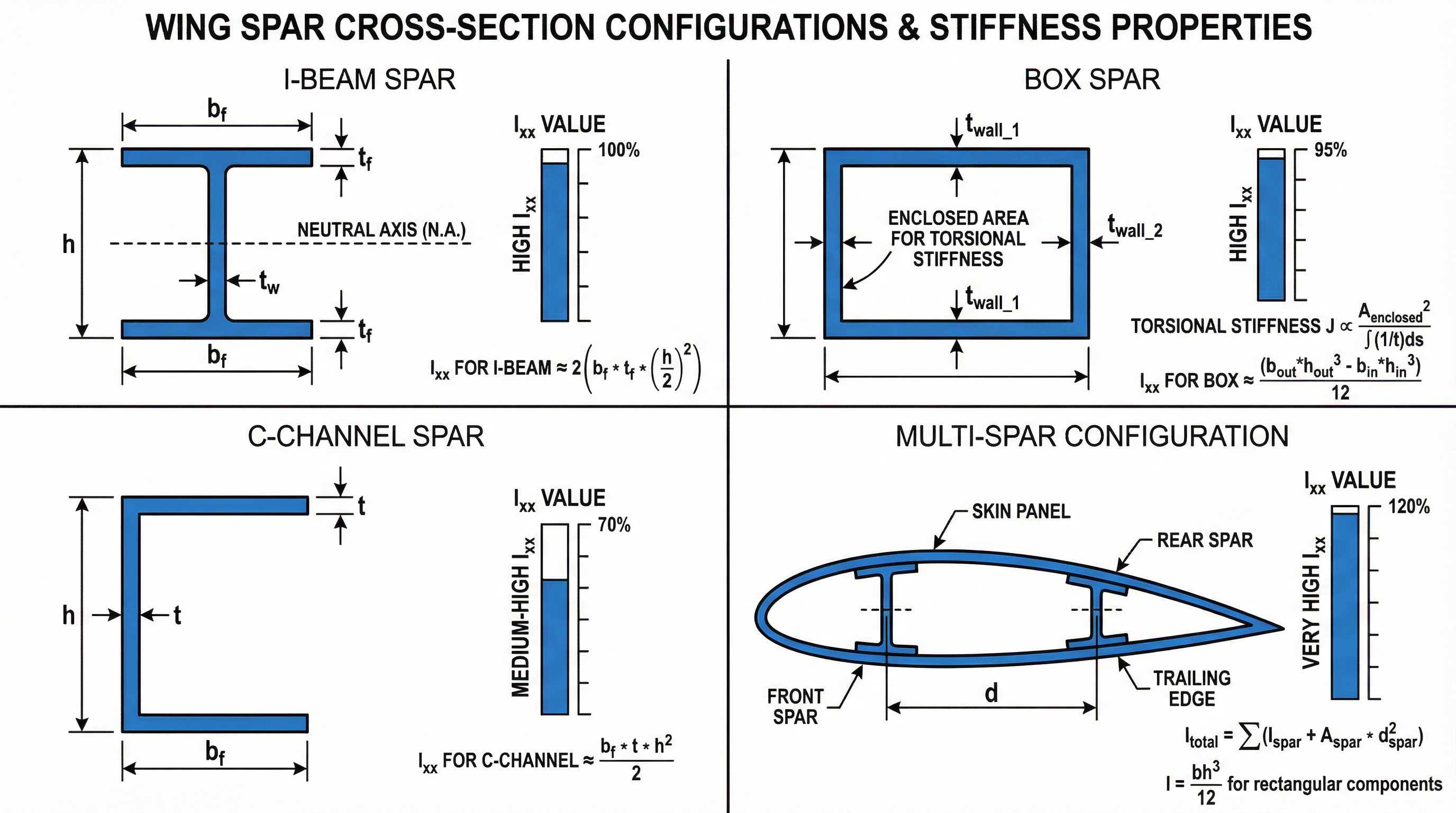
Figure 8: Comparison of different spar orientations and their effect on wing bending stiffness: I-beam, C-channel, box spar, and multi-spar configurations.
Fundamental Stiffness Relationship
Wing bending stiffness is governed by the area moment of inertia () of the cross-section about the bending axis:
For a rectangular section:
The cubic relationship with height means that increasing spar depth is far more effective than increasing width for improving bending stiffness.
Spar Configuration Comparison
Single I-Beam Spar:
Where = flange width, = total height, = web thickness, = flange thickness.
Box Spar (Closed Section):
Box spars provide:
- Higher torsional stiffness than open sections
- Better buckling resistance
- Integral fuel tank capability
Multi-Spar Configuration:
Using two or more spars increases total stiffness:
The parallel axis theorem contributions () can dominate when spars are well-separated.
Quick Stiffness Evaluation Method
For conceptual design, use these approximations to compare configurations:
Step 1: Estimate Equivalent Rectangular Section
Convert the actual spar to an equivalent rectangle with the same :
Step 2: Apply Configuration Factors
| Spar Type | Stiffness Factor (relative to solid rectangle) |
|---|---|
| Solid rectangle | 1.0 |
| I-beam (typical proportions) | 0.4–0.6 |
| Box spar | 0.5–0.7 |
| Multi-spar (2 spars) | 1.5–2.5 (depends on spacing) |
Step 3: Calculate Deflection Ratio
Hand Calculation Example
Problem: Compare wing tip deflection for a single I-beam spar vs. a two-spar configuration.
Given:
- Wing semi-span: m
- Distributed load: N/m
- Single spar: m⁴
- Two spars: Each m⁴, separated by 0.5 m, each with area m²
Solution:
Single spar stiffness:
Two-spar stiffness (using parallel axis theorem):
Stiffness ratio:
Deflection ratio:
Conclusion: The two-spar configuration is 7.25× stiffer, reducing tip deflection by 86%.
Design Guidelines for Spar Selection
| Design Goal | Recommended Approach |
|---|---|
| Maximum bending stiffness | Maximize spar height; use multi-spar with wide spacing |
| Torsional stiffness | Use closed sections (box spars); increase skin thickness |
| Weight efficiency | I-beam for pure bending; box for combined loading |
| Fuel volume | Box spars with integral tank design |
| Manufacturability | Consider access for fasteners and inspection |
Aeroelastic Considerations
Spar orientation affects not just static deflection but also:
- Divergence speed: Forward-swept wings require higher torsional stiffness
- Flutter: Bending-torsion coupling depends on elastic axis location
- Control reversal: Excessive twist under load can reverse aileron effectiveness
For conceptual design, ensure the elastic axis (determined by spar locations) is forward of the aerodynamic center to provide natural stability.
10. Applying These Concepts in Design Reviews
When performing conceptual design work or supporting design reviews, follow this systematic approach:
- Start with a free-body diagram — Isolate the system, define all forces and moments
- Explain load entry and reactions — Trace how loads enter, travel through members, and reach supports
- Discuss internal forces — Describe how axial, shear, and bending develop and influence design
- Identify critical joints — Mention connections, stress concentrations, and mitigation strategies
- Consider dynamic effects — Note if vibration or shock could alter the load path or require additional analysis
- Evaluate deflection and stiffness — Use hand calculations to verify FEA results and catch errors early
This structured approach demonstrates clear engineering thinking and physics-based reasoning that is essential for effective design communication.
Summary
Mastering structural engineering fundamentals requires understanding the interconnected concepts of equilibrium, free-body diagrams, internal forces, and load paths. Whether analyzing a simple beam or a complex aerospace structure, these principles remain constant:
| Concept | Key Equation | Application |
|---|---|---|
| Force Equilibrium | All static structures | |
| Moment Equilibrium | All static structures | |
| Axial Force | Tension/compression members | |
| Shear Force | Beam analysis | |
| Bending Moment | Beam analysis | |
| Cantilever Deflection | Wing/beam analysis | |
| Area Moment of Inertia | Stiffness calculations | |
| Dynamic Response | Vibration analysis |
By consistently applying these fundamentals and practicing clear communication of load paths and structural behavior, you'll build the engineering intuition needed for effective conceptual design work and design reviews.
References
- Bruhn, E.F. Analysis and Design of Flight Vehicle Structures. Tri-State Offset Company, 1973.
- Niu, M.C.Y. Airframe Structural Design. Conmilit Press Ltd., 1988.
- Megson, T.H.G. Aircraft Structures for Engineering Students. 6th ed., Butterworth-Heinemann, 2016.
- Timoshenko, S.P. and Gere, J.M. Mechanics of Materials. 2nd ed., PWS Engineering, 1984.
- Raymer, D.P. Aircraft Design: A Conceptual Approach. 6th ed., AIAA, 2018.